


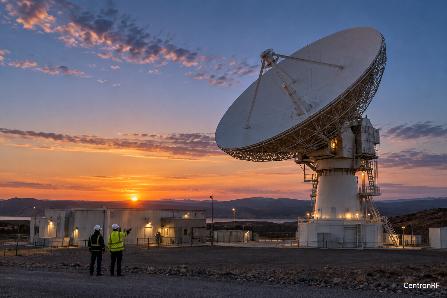
A coax protector listed to 3 GHz can only be considered for a ground-station route within that passband and its other ratings. The whole protection design must also be reviewed.
Why this matters in the industry
A ground station can contain RF sections at several frequencies and may carry DC along selected cables. The correct protector location depends on both the signal route and installation design.
The technical reasoning
Ground-station coaxial protection combines installation topology with RF and electrical requirements. Identify where the device lies in the station frequency plan and how the relevant protection path is arranged. A low-frequency coaxial segment may differ from the antenna's RF band, so the exact interface matters more than the site's broad satellite label.
Connecting engineering requirements with adequate evidence
An engineering requirement needs a stated quantity, operating conditions and a decision method. A descriptive label such as broadband, precision or rugged leaves those details unresolved. The evidence needed also depends on context: a laboratory demonstration, production screen, environmental evaluation and system qualification answer different questions. Documentation is useful when it identifies the actual method and conditions, rather than merely repeating a desired capability.
How to structure the investigation
Identify the protected lower-frequency route and its highest required frequency. Confirm DC passage, impulse specifications, environmental conditions and grounding instructions. Have the installation follow the approved site design, then verify RF response after assembly.
Translate the engineering question into measurable parameters and a scope of valid use. Identify which limits are established, which assumptions are made and which questions remain open. Link evidence to the exact configuration and revisions involved. Review exceptions before release and distinguish a requested document or planned test from evidence that has actually been supplied or completed.
Worked example or engineering scenario
A protection element inserted into a 1 GHz IF route needs IF suitability evidence. Its presence does not establish protection or RF compatibility for a separate Ka-band feed path.
Evidence to collect
| Record | Purpose |
|---|---|
| Check the local frequency | Defines the tested state and scope of the comparison. |
| Verify DC passage | Makes the stimulus or route condition reproducible. |
| Obtain grounding instructions | Supports interpretation of variation and possible confounding effects. |
| Follow the site design | Connects the observation with the stated engineering decision. |
Trade-offs and common interpretation errors
Do not promote a successful demonstration into a broad qualification claim. Likewise, paperwork cannot resolve a missing measurement model. A useful conclusion states what the evidence supports, what decision it informs and what additional observation would be needed to extend that conclusion to another configuration or environment.
What the result can support
Assess the actual segment and installation method rather than extrapolating across the complete station.
A lower-frequency coax protector should not be presented as direct Ku- or Ka-band protection.
Further technical reading
Related industry knowledge
- Satellite IF Cable Loss: Why Conversion Gain Is Not Enough
- Satellite Ground Receiver Overload: A Controlled Attenuation Check
Numerical scenarios are illustrative assumptions, not reported measurements of a supplied product or installation.