


At high attenuation, unwanted coupling around the attenuator may become larger than the intended transmitted signal. The measured result then reflects the setup's isolation.
How it works in practice
Sources of leakage include adjacent cables, open adapters, radiated coupling and instrument internal paths. A detector noise floor can also obscure the signal. Improve shielding and cable separation, terminate unused ports and verify the measurement system's dynamic range before interpreting a high dial setting.
Example and interpretation
A nominal 90 dB state cannot be confirmed if the fixture leaks a signal equivalent to only 65 dB of suppression.
Checks before use
- Measure the instrument floor
- Separate source and receive cables
- Inspect shielding and unused ports
- Repeat with a different source level
Important limit
A flat reading at high settings does not automatically mean the attenuator is defective.
Related Centron RF product
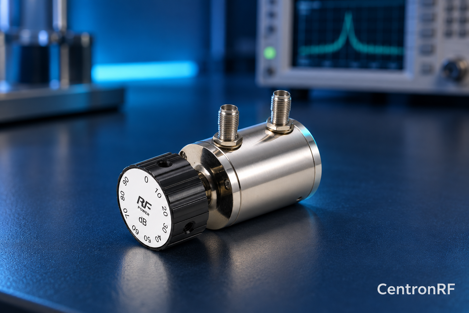
SMA rotary attenuator with 10 dB steps. The linked rotary model lists 0–90 dB adjustment in 10 dB steps, 50-ohm impedance and a DC–6 GHz band. Its listed continuous input is 2 W; obtain explicit switching and pulse limits before applying those stresses.
Further reading
Keysight: Accurate Network Measurements. This background reference explains general principles; the selected Centron RF model’s datasheet governs its own ratings.
Related guides
Educational guide. Numerical examples use the stated assumptions and are not test results for a supplied unit.