


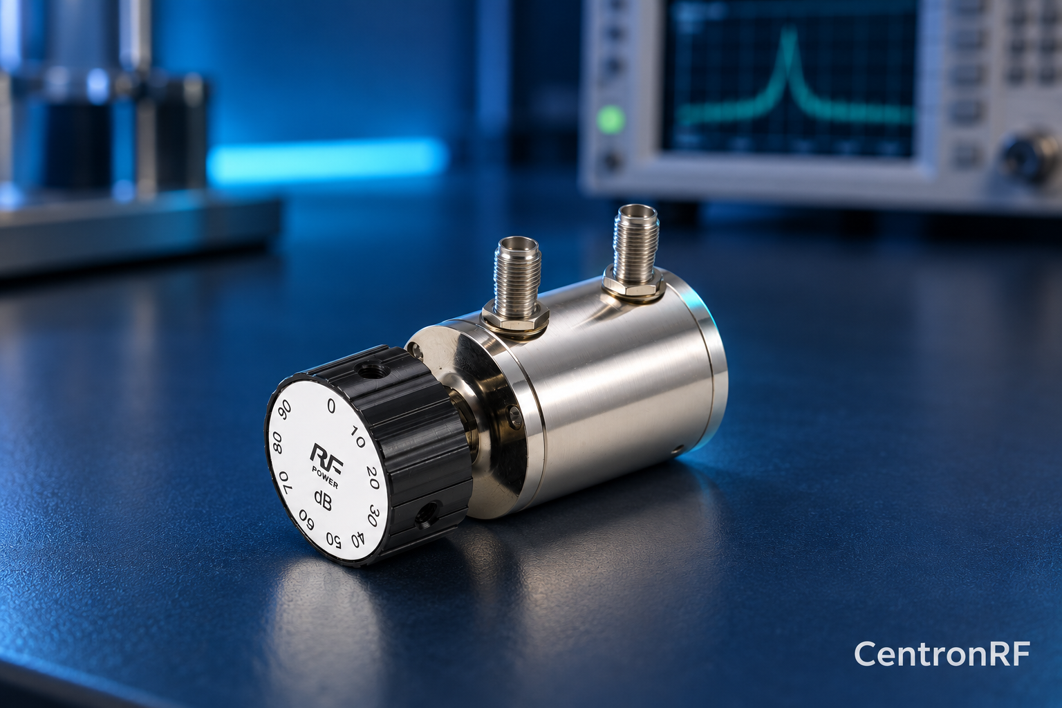
Measure the through loss at the zero setting to establish a useful reference. The zero label usually describes the selected attenuation state, not necessarily total loss.
How it works in practice
Cable and connector losses remain when the dial is at zero. Compare each selected state against either the measured zero reference or the entire calibrated path, and state which convention you use. This avoids counting baseline insertion loss twice when calculating receiver input power.
Example and interpretation
If the zero path measures 0.7 dB and a selected state measures 10.9 dB total loss, the change from zero is 10.2 dB.
Checks before use
- Measure zero-state loss
- Measure the selected state
- Choose a reporting convention
- Include frequency and uncertainty
Important limit
Do not subtract baseline loss in one part of a report and include it in another.
Related Centron RF product
SMA rotary attenuator with 10 dB steps. The linked rotary model lists 0–90 dB adjustment in 10 dB steps, 50-ohm impedance and a DC–6 GHz band. Its listed continuous input is 2 W; obtain explicit switching and pulse limits before applying those stresses.
Further reading
Keysight: Accurate Network Measurements. This background reference explains general principles; the selected Centron RF model’s datasheet governs its own ratings.
Related guides
- Why High Attenuation Measurements Can Be Limited by Leakage
- Two-Dial Attenuators: Understanding Series and Parallel Product Names
Educational guide. Numerical examples use the stated assumptions and are not test results for a supplied unit.