


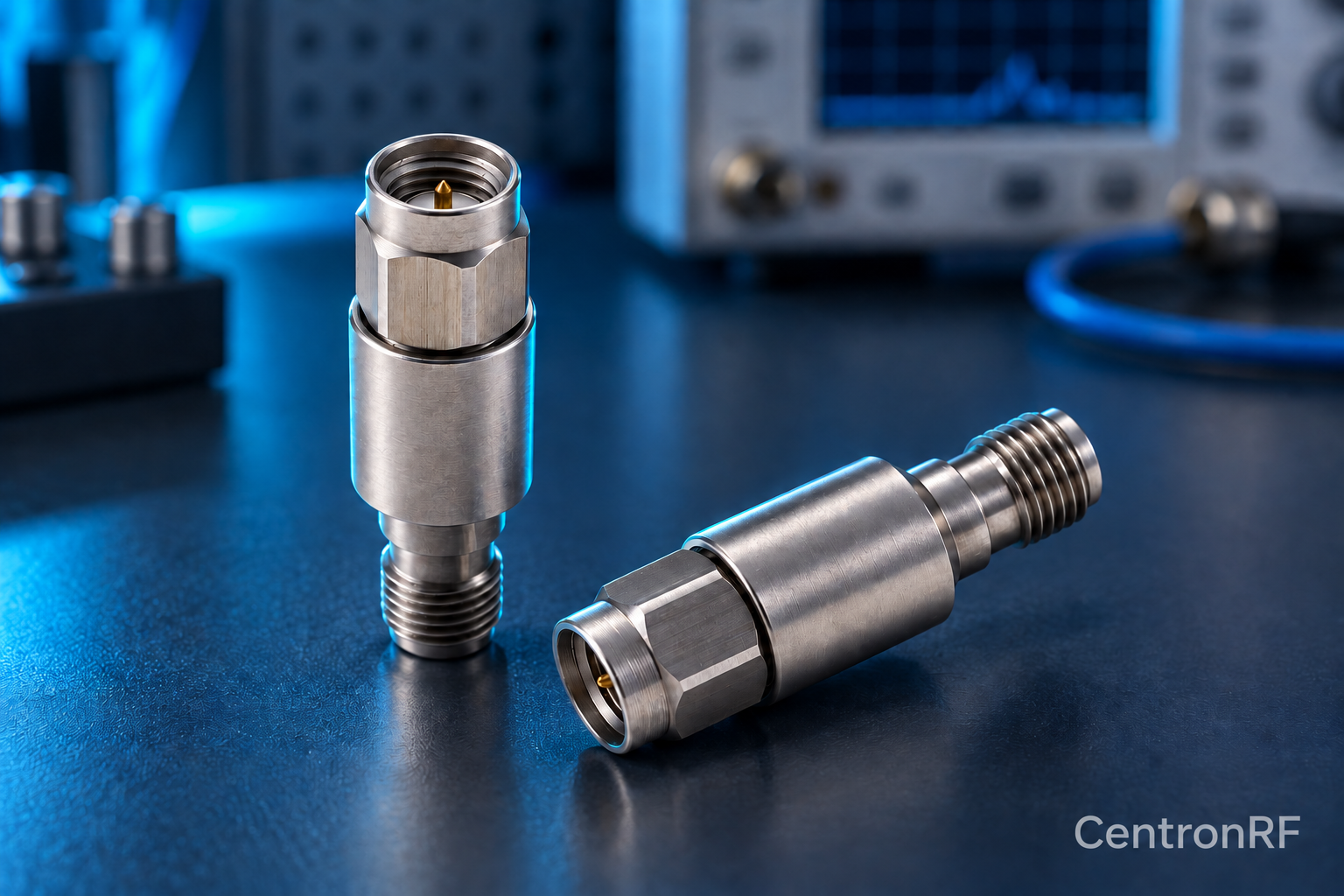
Unexpected RF loss can result from the pad, its connection, the correction method or a damaged supporting component. Test one variable at a time.
How it works in practice
Begin with low-power measurements and a known reference path. Inspect connector pins and mating surfaces, verify the selected attenuation value, and compare loss over frequency. Substitute a known-good cable or pad only after recording the original conditions. A frequency-selective anomaly may indicate an adapter or connector problem rather than incorrect nominal loss.
Example and interpretation
If measured loss changes when the cable moves, investigate cable integrity and connector strain before concluding that the attenuator value is wrong.
Checks before use
- Record the original setup
- Check connectors without power
- Measure a reference through path
- Substitute one component and compare
Important limit
Do not compensate a damaged connection with an unexplained correction factor.
Related Centron RF product
SMA 5 W 6 GHz fixed attenuator. The SMA 5 W model is listed as a 50-ohm fixed attenuator with a DC–6 GHz range. Select an available attenuation option and verify the current tolerance, cooling conditions and pulse limits for your application.
Further reading
Keysight: Spectrum Analysis Basics. This background reference explains general principles; the selected Centron RF model’s datasheet governs its own ratings.
Related guides
- RF Attenuator Inspection and Care Before Connection
- How to Choose an RF Attenuator: Power, Bandwidth and Connectors
Educational guide. Numerical examples use the stated assumptions and are not test results for a supplied unit.