


Choose an RF attenuator by checking required loss, maximum input power, operating frequency, impedance and connector compatibility together. A dB value alone cannot establish suitability.
How it works in practice
Begin at the device you need to protect and work backward to the source. Include the highest expected source level, startup transients and cable loss. Distinguish the attenuator's average input rating from the much smaller power at its output. Then check the manufacturer's thermal conditions and attenuation tolerance across your band.
Example and interpretation
A 1 W source is 30 dBm. A nominal 20 dB pad produces about 10 dBm in a matched path, while dissipating approximately 0.99 W.
Checks before use
- Write the maximum source level
- Calculate required attenuation
- Check input and pulse ratings
- Verify connectors and frequency range
Important limit
Do not select a low-power pad merely because the calculated output is small.
Related Centron RF product
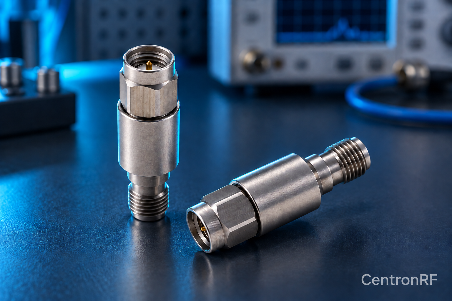
SMA 5 W 6 GHz fixed attenuator. The SMA 5 W model is listed as a 50-ohm fixed attenuator with a DC–6 GHz range. Select an available attenuation option and verify the current tolerance, cooling conditions and pulse limits for your application.
Further reading
Keysight: Spectrum Analysis Basics. This background reference explains general principles; the selected Centron RF model’s datasheet governs its own ratings.
Related guides
Educational guide. Numerical examples use the stated assumptions and are not test results for a supplied unit.